
Agroui, K., A. Belgachi and S. Kadri, 2003. Caractérisations électriques et thermiques d'un module PV au silicium multicristallin en milieu contrôle et sur site saharien. Rev. Energ. Ren.: ICPWE, 2003, pp: 19-25.
Research Journal of Applied Sciences, Engineering and Technology
External Magnetic Field and Air Mass Effects on Carrier’s Effective Lifetime of a Bifacial Solar Cell under Transient State
Research Journal of Applied Sciences, Engineering and Technology 2020 17: 140-146
Cite This ArticleAbstract
This paper presents a theoretical study of the external magnetic field and the air mass effects on the carrier density, the transient open circuit voltage decay and the effective minority carrier’s lifetime in a polycrystalline silicon solar cell. From a theoretical approach based on the columnar model of the grains and the quasi-neutral base, the three-dimensional diffusion equation is established and the boundaries conditions are defined in order to use Green’s functions to solve this equation. New analytical expressions of carrier’s density and transient voltage are also found. The magnetic field and the air mass impacts on transient electrons density and transient open circuit voltage are then analyzed. The effective minority carrier lifetime is extracted from the curve versus time of transient open circuit voltage decay for different values of magnetic field and air mass.
Keywords:
Introduction
In order to reduce dependence on fossil fuels, renewable energy sources have been studied intensively for many years (Ellabban et al., 2014). As solar energy, one major source of renewable energies, depends on the fluctuating solar radiation and solar cell properties.
However, some external factors as magnetic field (Betser et al., 1995; Erel 2002; Madougou et al., 2007) external electric field (Coors et al., 1998; Pelanchon et al., 1992; Dieng et al., 2009), intense light (Pelanchon et al., 1992; Agroui et al., 2003) and internal factors as grain size (Samb et al., 2009), grain boundary recombination velocity (Ba et al., 2003), air mass (Rida et al., 2016; Shnishil et al., 2011) electric field in the bulk due to carrier concentration (Pelanchon et al., 1992) can influence the solar cell quality.
In this study, we present a three-dimensional study of a bifacial solar cell under external variable magnetic field and air mass. From a theoretical approach, the calculations were carried out in the case of a polycrystalline device with columnar model of grain orientation under front side illumination and the quasi-neutral base. The three dimensional diffusion equation is established and the boundaries conditions are defined in order to use Green’s functions to solve this equation.
In this approach, new analytical expressions of excess minority carriers density and transient open circuit voltage were established for a front side illumination.
The effects of magnetic field and air mass on excess minority carriers generation, transient voltage decay and effective lifetime profile are then analyzed.
Materials And Methods
In this study based on a 3D modeling of a polycrystalline silicon solar cell; we made the following hypothesis:
- Considering the weak thickness of the emitter and zone of space load, we neglected their contributions to the photocurrent, so the quasi-totality of the current is provided therefore by the base (Charles et al., 2000; Toure et al., 2012).
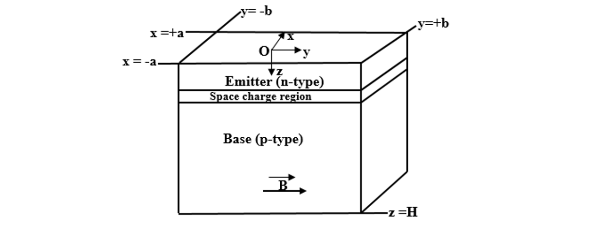
- The grains are under parallelepipedic shape (2a; 2b; H) and the joints of grains are perpendicular to the junction.
- The surfaces between two adjacent grains and perpendicular to the junction are characterized by the same carrier recombination process evaluated by a grain boundaries recombination velocity
. - The electric field of crystal lattice is negligible (Sam et al., 2012).
- Only the contribution of the base in the process of generation is considered.
- The magnetic field is oriented according to the direction
- The illumination is uniform. Then we have a generation rate depending only on the depth in the base z.
- The solar cell is front side illuminated under the external magnetic field with the tree type of air mass is illustrated on Fig. 1 (Sam et al., 2016).
In the base of the cell, the excess minority carriers are electrons and their density satisfies to the equation below:
Substituting Eq. (2) into (1) and taking into account the assumption of quasi-neutrality of the base, the diffusion equation of the electrons in the base becomes the equation:
where,
and,
D* is the diffusion coefficient of excess minority carriers in the base of the bifacial cell in presence of magnetic field (Dieng et al., 2011; Flohr and Helbig 1989); it can be expressed as:
The presence of the magnetic field in our model leads to new values of carrier’s diffusion length
The carriers’ generation rate under multispectral light at the depth z in the base can be written by the following expression:
In this expression of
The coefficients am and bm are the modeling coefficients of AM1.5, AM1 and AM0 of air mass (Mohammad 1987; Furlan and Amon 1985).
Equation (1) is solved with the following boundary conditions:
- At the junction z = 0:
- At the rear side z = H:
- At surfaces limited by x = ±a and y = ±b
a, b and H are the grain sizes as indicated on Fig. 1.
A solution of Eq. (1) is given by Eq. (11) according to the author of the reference (Sam et al., 2016):
where,
The quantities
The transient voltage decay is defined by:
where,
and,
The quantities
According to expression (18), we notice two types of
- If:
The time dependent tension is rewritten in the following way Eq. (26):
This is a linear function of the time with a negative slope
- If:
Results And Discussion
We present here the simulation results obtained from the previous modeling equations by using the Origin pro and Mathcad software.
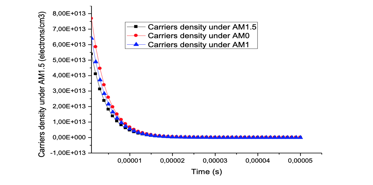
Effects of magnetic field and air mass on carrier density: Figure 2 and 3 present respectively curves of carrier’s density versus air mass and versus magnetic field. This figure shows a quasi-exponential decay versus time of the electrons density.
This decay of the Fig. 2 can be explained by the reducing of the generation rate during the time to the different air mass. So, when the air mass increases, the direction of normal irradiance decreases reducing carriers’ generation.
A quantitative difference is observed on the curves corresponding to these three values of air mass. These differences are more sensitive on the amplitudes of the curves, i.e., during the illumination phase. So, hole-electron pair generation rate and air mass number varies in reverse.
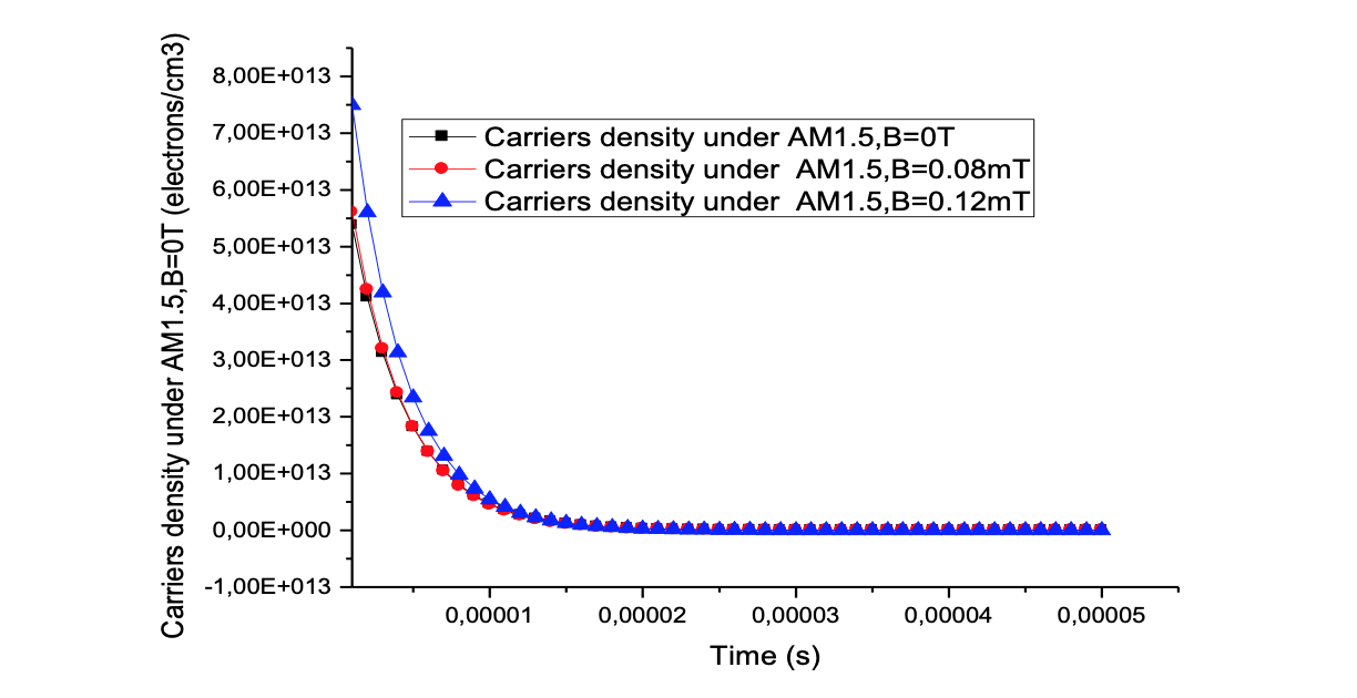
Figure 3 presents the variation of carriers’ density versus magnetic field and time. These curves show that for magnetic field increase, the maximum of the excess minority carriers density increases also and are shifted left to the junction. This increasing of the maximum of the excess minority carriers density translate an increase of the carrier concentration.
The increase of carriers density cross to the junction with the magnetic field is more important; so this displacement of the maximum of the excess minority carriers’ density shows that there is a decrease of carriers flow through the junction. We can also explain this by the reducing of recombination at the grain boundaries because of the magnetic field.
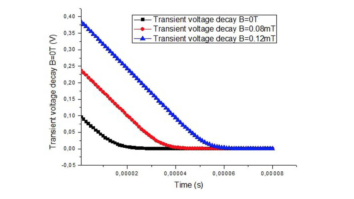
Effects magnetic field and air mass on transient voltage: We use the expression of transient voltage to show the influence of air mass and magnetic field on transient voltage by the following figures.
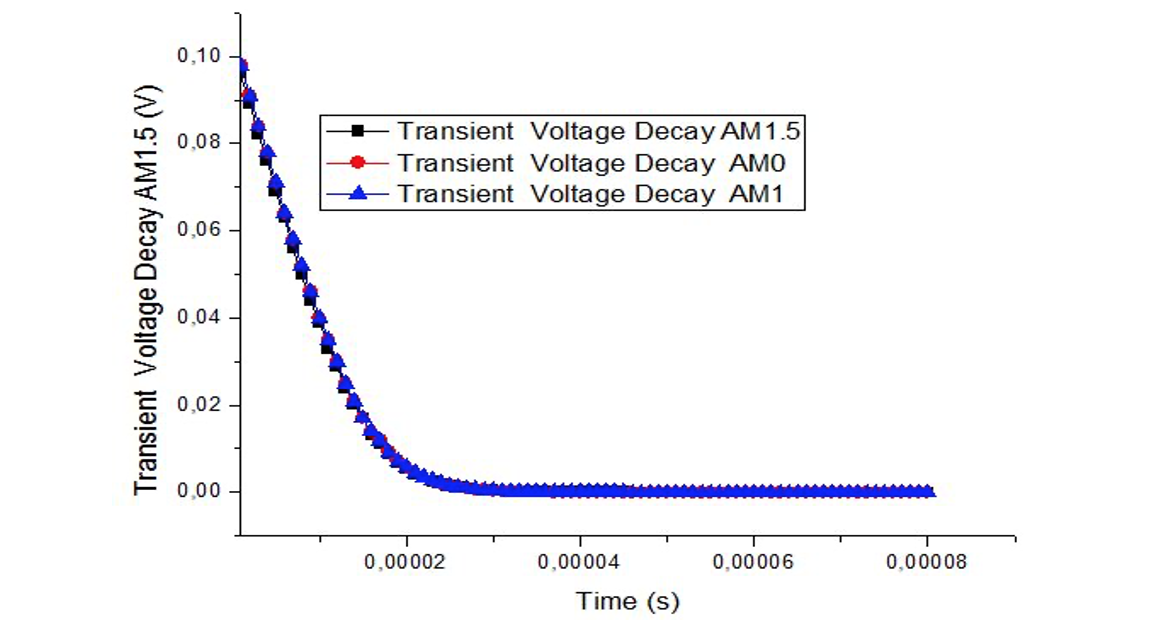
Figure 4 presents the curve of transient voltage decay when the air mass number air increases but we observe the same variation for air mass 0 and 1. This behavior is explained by the substantially identical values of air mass 0 and air mass 1.The decrease of transient voltage to air mass 0 to air mass 1.5 is explained by an important photogeneration of excess minority carriers under AM0 than AM1.5.
The increase of air mass creates the decrease of normal irradiance by reducing illumination then the number of excess minority carriers. In other words, much charge carriers are stored near the junction under air mass 0 because much carriers are photo-generated. The profile of Fig. 5 presents the transient voltage increase when the magnetic field increases.
The transient voltage which means an accumulation of charges across the junction presents a maximum for very low Sf values (open circuit). The open circuit voltage increases with increasing magnetic field. This is a consequence of charges accumulation in the base and the diminution of junction recombination with increasing magnetic field. This phenomenon is accompanied by an increase of recombination in the bulk and to grain boundaries (Dieng et al., 2011; Zoungrana et al., 2007).
The behavior of the transient voltage under magnetic field characterizes an increase of resistive losses in the base (due to material structure and electrical grids). This increase of resistive losses leads to a decrease in the output voltage.
Effects of magnetic field and air mass on effective lifetime: The Eq. (26) gives the effective lifetime and permit us to obtain the values of effective lifetime by making linear fitting with the software of origin lab of the linear expression of transient voltage decay:
where,
We use this form of transient open circuit voltage because the linear parts of the curves don’t present capacitance effects. The results of linear fitting are saving on the Table 1.
Table 1 shows the variation of effective lifetime versus magnetic field and air mass. The study of carriers’ density and transient voltage show that the air mass AM0 has the maximum of carriers which permit to obtain the transient voltage that we make the linear fitting to get values of effective lifetime.
The increase of magnetic field explains the decreasing of diffusion length and diffusion coefficient. This reducing of diffusion length and diffusion coefficient is responsible of this decreasing because the minority of carriers’ recombination is fast. So the time of recombination becomes short when the magnetic field increases. All these situations are responsible of the decreasing of effective lifetime.
Another analysis of this Table 1 presents an inchange of effective lifetime versus air mass number increase because the effective lifetime is independent on the generated rate or the photogeneration globally.
We notice that the effects of air mass are less important than the magnetic field. The same results of effective lifetime with the magnetic field are found by Sam et al., (2016).
| Illumination mode | Air mass | |||
|---|---|---|---|---|
| Front side illumination | AM0 | 4.33 | 3.71 | 3.25 |
| AM1 | 4.33 | 3.71 | 3.25 | |
| AM1.5 | 4.33 | 3.71 | 3.25 |
Conclusion
In this study, a three dimensional approach of electrons diffusion in the p region of a polycrystalline silicon solar cell is presented. The solar cell is front side illuminated by a pulsed light under external magnetic field versus air mass values. The resolution of the time dependent and the three dimensional diffusion equation leads to new expressions of the transient voltage and the reduced amplitude of transient voltage.
This study shows the effects of air mass and magnetic field on carriers density, transient voltage decay and carriers effective lifetime. In summary, the limiting effects of magnetic field on the quality of solar cell are pronounced. The air mass does not affect the solar cell carriers effective lifetime.
Author Details
1Laboratoire de Matériaux et Environnement, UFR/ST, Université Joseph Ki-Zerbo de Ouagadougou, 03 BP 7021 Ouagadougou 03, Burkina Faso
2Departement de Physique, UFR/ST, Université Nazi Boni de Bobo-Dioulasso, 01 BP 1091 Bobo 01, Burkina Faso
References
Ba, B., M. Kane and J. Sarr, 2003. Modelling recombination current in polysilicon solar cell grain boundaries. Sol. Energ. Mat. Sol. C., 80: 143-154.
Betser, Y., D. Ritter, G. Bahir, S. Cohen and J. Sperling, 1995. 3D study of bifacial silicon solar cell under intense light. App. Phys. Lett., 67(13): 1883-1884.
Charles, J.P., A. Haddi, A. Maouad, H. Bakhtiar, A. Zerga, A. Hoffmann and P. Mialhe, 2000. La jonction, du solaire a la microelectronique. Rev. Energ. Ren., 3: 1-16.
Coors, S., B. Schneider and M. Bohm, 1998. 2nd World Conference and Exhibition on Photovoltaic Solar Energy Conversion.
Dieng, A., I. Zerbo, M. Wade, A.S. Maiga and G. Sissoko, 2011. Three-dimensional study of a polycrystalline silicon solar cell: The influence of the applied magnetic field on the electrical parameters. Semicond. Sci. Tech., 26(9).
Dieng, A., M.L. Sow, S. Mbodji, M.L. Samb, M. Ndiaye, M. Thiame, F.I. Barro and G. Sissoko, 2009. 3D study of a polycrystalline silicon solar cell: Influence of applied magnetic field on the electrical parameters. Proceeding of 24th European Photovoltaic Solar Energy Conference and Exhibition. September 21-25, Hamburg, Germany, pp: 473-476.
Ellabban, O., H. Abu-Rub and F. Blaabjerg, 2014. Renewable energy resources: Current status, future prospects and their enabling technology. Renew. Sust. Energ. Rev., 39: 748-764.
Erel, S., 2002. The effect of electric and magnetic fields on the operation of a photovoltaic cell. Sol. Energ. Mat. Sol. C., 71(2): 273-280.
Flohr, T. and R. Helbig, 1989. Determination of minority-carrier lifetime and surface recombination velocity by optical-beam-induced-current measurements at different light wavelengths. J. Appl. Phys., 66(7): 3060-3065.
Furlan, J. and S. Amon, 1985. Approximation of the carrier generation rate in illuminated silicon. Solid State Electron., 28(12): 1241-1243.
Madougou, S., F. Made, M.S. Boukary and G. Sissoko, 2007. I-V characteristics for bifacial silicon solar cell studied under a magnetic field. Adv. Mater. Res., 18-19: 303-312.
Mohammad, S.N., 1987. An alternative method for the performance analysis of silicon solar cells. J. Appl. Phys., 61(2): 767-772.
Pelanchon, F., C. Sudre and Y. Moreau, 1992. Solar cells under intense light concentration: Numerical and analytical approaches. Proceeding of 11th European Photovoltaic Solar Energy Conference. Montreux, October 12-16, pp: 265-267.
Rida, K.S., A.A.K. Al-Waeli and K.A.H. Al-Asadi, 2016. The impact of air mass on photovoltaic panel performance. Eng. Sci. Rep., 1(1). Doi:10.18282/ser.v1.i1.41.
Sam, R., B. Zouma, F. Zougmoré, Z. Koalaga, M. Zoungrana and I. Zerbo, 2012. 3D determination of the minority carrier lifetime and the p-n junction recombination velocity of a polycrystalline silicon solar cell. Proceeding of IOP Conference Series: Materials Science and Engineering, 1st International Symposium on Electrical Arc and Thermal Plasmas in Africa (ISAPA), October 17-22, Ouagadougou, Burkina Faso, Vol. 29.
Sam, R., K. Kabore and F. Zougmore, 2016. A three-dimensional transient study of a polycrystalline silicon solar cell under constant magnetic field. Int. J. Eng. Res., 5(2): 93-97.
Samb, M.L., M. Dieng, S. Mbodji, B. Mbow, N. Thiam, F.I. Barro and G. Sissiko, 2009. Recombination parameters measurement of silicon solar cell under constant white bias light. Proceeding of 24th European Photovoltaic Solar Energy Conference. Hambourg, Germany, pp: 469-472.
Shnishil, A.H., S.S. Chid, M.J. Yaseen and T.J. Alwana, 2011. Influence of air mass on the performance of many types of PV modulus in Baghdad. Energ. Procedia, 6: 153-159.
Toure, F., M. Zoungrana, B. Zouma, S. Mbodji, S. Gueye, A. Diao and G. Sissoko, 2012. Influence of magnetic field on electrical model and electrical parameters of a solar cell under intense multispectral illumination. Global J. Sci. Frontier Res. Phy. Space Sci., 12(6).
Zoungrana, M. et al., 2007. 3D Study of bifacial silicon solar cell under intense light concentration external constant magnetic field: Effect of magnetic field and base depth on excess minority carrier generation. J. Sci., 7(4): 73-81.
Rights and permissions
Open Access: This article is licensed under a Creative Commons Attribution 4.0 International License, which permits use, sharing, adaptation, distribution and reproduction in any medium or format, as long as you give appropriate credit to the original author(s) and the source, provide a link to the Creative Commons license, and indicate if changes were made. The images or other third-party material in this article are included in the article’s Creative Commons license, unless indicated otherwise in a credit line to the material. If material is not included in the article’s Creative Commons license and your intended use is not permitted by statutory regulation or exceeds the permitted use, you will need to obtain permission directly from the copyright holder. To view a copy of this license, visit http://creativecommons.org/licenses/by/4.0/
Cite this Article
Alain Diasso, Raguilignaba Sam and François Zougmoré, 2020. External Magnetic Field and Air Mass Effects on Carrier’s Effective Lifetime of a Bifacial Solar Cell under Transient State. Research Journal of Applied Sciences, Engineering and Technology 17: 140-146 http://doi.org/10.19026/rjaset.17.6026
Received
Accepted
Published
April 18, 2020
May 8, 2020
August 25, 2020
DOI: http://doi.org/10.19026/rjaset.17.6026
Sections
Abstract
Keywords
Introduction
Materials And Methods
Results And Discussion
Effects of magnetic field and air mass on carrier density
Effects magnetic field and air mass on transient voltage
Effects of magnetic field and air mass on effective lifetime
Conclusion
Author Details
References
Rights And Permissions
Cite This Article