
Banwell, P.E. and L. Téot, 2003. Topical Negative Pressure (TNP): The evolution of a novel wound therapy. J. Wound Care, 12(1): 22-28.
Research Journal of Applied Sciences, Engineering and Technology
A Portable Device for Wound Healing with Self-charging Capability
Research Journal of Applied Sciences, Engineering and Technology 2020 17: 35-39
Cite This ArticleAbstract
Herein, a portable device for wound healing with self-charging capability has been proposed by utilizing embedded system technology with an electromagnetic energy harvester. With the storing capability, the harvester can generate electricity from human vibration. By enhancing the coil turns and speed of the magnet, the generation rate of the harvester can be increased. The vacuum environment can be easily established by a vacuum pump. According to the negative pressure sensor’s data, the environment can be easily stabilized by applying Pulse Width Modulation (PWM) signal to the pump driver. By using adhesive drape, the wound surface can be easily fitted with the fluid container. The device can be used at indoor and outdoor environment uninterruptedly.
Keywords:
Introduction
The large growing old population is teased with an increasing range of acute and chronic, non-healing wounds, generally ascribable to the surge in type 2 diabetes. Diabetic patients have 12 to 25% risk of foot ulcers and they have 15-times greater risk for foot mutilations than non-diabetics. The complex operation, radiation therapy, immunosuppression, severe infection resistance to an antibiotic and pressure sores are the major causes for the wounds (Scherer et al., 2008). During the last two decades, many wound interventions have been developed to simplify the healing by focusing on maintenance of wound moisture, reduction of bacterial and nonviable tissue burdens and management of proteases and cytokines and by stimulating of growth elements (Kloth 2014). Vacuum-Assisted Closure (VAC) is a highly new technology to manipulate severe and chronic wounds. It is known as many anonyms such as NPWT (Negative Pressure Wound Therapy), TNP (Topical Negative Pressure) SPD (Sub-atmospheric Pressure) VST (Vacuum Sealing Technique) and so on (Banwell and Téot 2003). The inventors of the VAC technology experimented with pigs and found that the efficient rate of blood flows at the wound surface of the pigs with a -125mmHg vacuum environment but the blood flow gradually decreased within 5-7 min at room pressure at 400 mmHg. After this, with re-establishment of the vacuum environment at -125 mmHg, the blood flow increased again (Morykwas et al., 1997; Lambert et al., 2005). According to the principle, many portable NPWT devices are being developed with optimum 5 min ON time and 2 min OFF time for the usage of it at indoor and outdoor environment such as Nisus touch NPWT system, Avelle NPWT system (Duteille et al., 2018) and so on. These devices are battery operated and need to recharge after a certain period. Although the devices are beneficial for wound healing, there is no self-charging capability. Discontinuous of operation due to the less storage capacity of the devices is responsible for interrupting the wound healing process.
In this contribution, we present a self-charging portable NPWT device which has the capability of charging itself by harvesting electricity from unused vibration energy.
Methodology
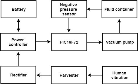
Figure 1 presents the schematic diagram of the proposed device. The device consists of a vacuum pump, a negative pressure sensor, a fluid container, an energy harvester module and a power control module with a PIC16F72 microcontroller. The pump was used to create a vacuum environment where the negative pressure sensor was used to sense and measure the environment. The microcontroller is an 8-bit programmable Integrated Circuit (IC) which has a maximum of 20Megahertz (MHz) clock frequency (Makarov et al., 2016) and it was used for data processing. On the other hand, the fluid container was used to collect and store the fluid from the wound surface. For the uninterrupted power supply, an electromagnetic energy harvester module was used which can generate electricity from human vibration. The power control module was used for charging control of the battery and regulating the power so that the device can be operated uninterruptedly.
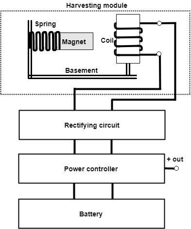
Figure 2 demonstrates a schematic diagram of the energy harvesting unit. The unit consists of an electromagnetic energy harvesting module, rectifier, power controller and a battery. The harvesting module was designed with a series of Neodymium strong permanent magnet and copper wire which size was 0.26 mm in diameter for generating efficient power from human movement. In this module, the coil and the spring with magnet were placed on the insulating basement. The coil section is unmovable where the magnet can move easily with the help of the spring. Because of the potential energy of the spring, the displacement of the speed can be enlarged. According to Faraday's law of induction, the harvester can generate electricity when the magnet swings in front of the coil. The voltage induced in the coil can be measured by the following equation (Galili et al., 2006):
where,
The amplitude of the induced voltage of the coil is directly proportional to the displacement speed of the magnet. When vibration occurs in the harvester it produces electricity. After rectifying the generated electricity with the help of the rectifying circuit, the power controller circuit store this in the battery and distribute the electricity to the whole system. Thus, the battery of the proposed device can be charged up.
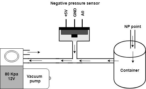
Figure 3 represents the schematic diagram of the NPWT unit. In this section, the vacuum pump was connected to the fluid collecting container via a silicon pipe where a negative pressure sensor was kept between the pump and the container for measuring the negative pressure. The pump can have the functionality to create maximum negative pressure which is -80 kilopascal (kPa) or -600 mmHg (Tan et al., 2017). This negative pressure is larger than the design specification of -125 mmHg with the motive of supplying appropriate negative pressure. The sensor was designed only for measuring negative pressure in the range of 0 to -205 mmHg and it has 3-pins such as VCC, GND and A0. Concerning the negative pressure level, the sensor gives an analog value from 0 to 975. When the pump turns ON, the sensor measures the negative pressure and send the analog value to the microcontroller. According to the sensor’s feedback, the negative pressure can be controlled by way of applying Pulse Width Modulation (PWM) signal through the PIC16F72 microcontroller to the pump driver. The PWM signal can control the motor speed by turning a digital output which turns OFF and ON the pump for a certain duration. Besides this, the fluid container was designed to withstand the maximum negative pressure for a long duration. The Negative Pressure (NP) point of the container was used to connect the suction unit to the wound surface so that fluid can easily enter into the container.
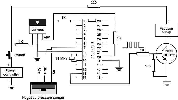
Figure 4 indicates the circuit diagram of the proposed device. In this segment, the power module was connected to the LM7805 voltage regulator through a switch and 1k resistor for providing constant +5 volts in output where the output terminal of the regulator was connected to 1-number pin of the PIC16F72 microcontroller through another 1k resistor so that the microcontroller can be turned ON. The negative pressure sensor’s A0 pin was connected to 7-number pin for calculating negative pressure inside the container which was created by the vacuum pump. A TIP122 NPN transistor was connected to 13-number pin through 1k and 10K resistor so that the speed of the pump can be controlled by applying PWM signal. The PWM signal varies according to the negative pressure sensor data so that the pressure can be kept in constant.
Results And Discussion
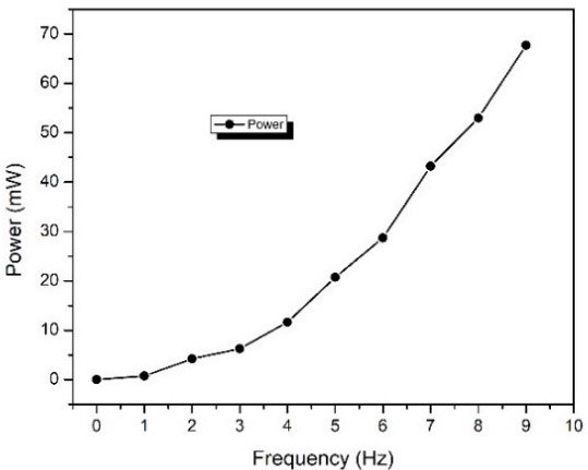
The harvesting module was tested in a laboratory environment with multiple vibration frequencies and found that the induced voltage changes according to the changes in the vibration frequency. Figure 5 indicates the graph of frequency versus output power of the harvester on different frequencies. By using the Eq. (1), we have measured the induced voltage and found that the output power of the harvester which was 0.75 mW at frequency 1 Hz. At frequency 2 Hz, 4.18 mW power was obtained. We have also found that the maximum output power of the harvester was about 67.71 mW at frequency 9 Hz. The proposed device was also tested in an outdoor environment and found that nearly 1.5 watts of electricity can be produced after walking 100 m with gentle movement.
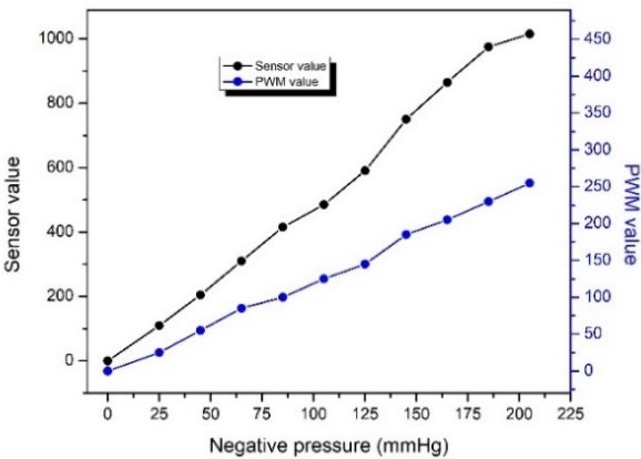
The negative pressure was tested which was generated by the vacuum pump. The pressure was controlled by applying the PWM signal to the pump driver through the PIC16F72 microcontroller. Figure 6 demonstrates the graph of PWM value versus negative pressure. By varying the PWM value, the sensor’s value and the negative pressure can be altering from 0 to 1015 and 0 to -205 mmHg respectively. By using an analog vacuum gauge, we had measured the sensor’s value 110 at 25 PWM when the vacuum gauge showed the pressure level at -25 mmHg.
The changing of the negative pressure level according to the PWM value was nonlinear. For the reason, we had found the sensor’s value 205 at 55 PWM value when the vacuum gauge showed pressure level at -45 mmHg. For 145 PWM value, we had measured the sensor’s value and negative pressure which were 590 and -125 mmHg respectively. Thus the maximum pressure -205 mmHg and sensor’s maximum value 1015 were measured for 255 PWM value.
For the design specification of the NPWT system, the PWM value was set at 145. If any air leakage occurs in the NPWT system during operation, the microcontroller increases the PWM value from 145 to 255 until the sensor’s value reach at 590 and thus the negative pressure can be kept in constant automatically.
Table 1 indicates the implemented results of the proposed device on different age’s patients. The data were tabulated for the patients who were 52 to 85 years old. The patients were selected from the records of a wound healing center from January 2019 to Jun 2019. Total twenty records were found within the duration. Among them, five records were fulfilled the inclusion criteria and exclusion criteria. In inclusion criteria, the patients were selected based on ages which were 65 to upward and who had wounds caused by diabetic foot ulcer and vascular ulcer.
On the other side, in exclusion criteria, less than 65 years old patients and wounds by accidental or except diabetic foot ulcer and vascular ulcer were selected. In the table, before starting the wound healing process the patient who was 52 years old and had S1 sized wound which was 2 cm2. After running the healing process, the wound became S2 sized which was at 0.5 cm2 in 216 h of operation. For the patient who was 62 years old, after the healing process, we have found 67% of improvement in 504 h of operation. Thus we have found different percentages of improvement after implementing the proposed device to the patients. The healing process took long duration according to the patient’s age and wound surface location.
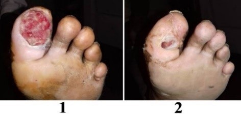
Figure 7(1) indicates the optical image of the wound surface condition before the healing process and Fig. 7(2) indicates the condition after the healing process in the long duration. The wound surface which is shown in the figure was captured from a patient who was 85 years old and who fulfilled the inclusion criteria. The patient had 6 cm2 sized wound before starting the healing process. The improvement of the wound surface has found 95% after 1872 h of operation.
Table 2 indicates the comparison of different NPWT devices which are available in the market. The existing devices can create maximum pressure from 0 to -200 mmHg whereas the negative pressure range of PRO-II is about -50 to -200 mmHg (Tan et al., 2017). Although they have enough range of negative pressure level, all the devices have no self-charging capability.
| Age | Hours | Dressing | S1 (cm2) | S2 (cm2) | Improvement (%) |
|---|---|---|---|---|---|
| 52 | 216 | 13 | 2 | 0.5 | 75 |
| 62 | 504 | 17 | 3 | 1.0 | 67 |
| 65 | 1512 | 35 | 7.5 | 0.5 | 93 |
| 75 | 1296 | 30 | 6 | 2.3 | 63 |
| 85 | 1872 | 38 | 6 | 0.3 | 95 |
| Manufacturer | Product | Specifications |
|---|---|---|
| KCL | V.A.C.® Freedom | Not self-charging Pressure range: -50 to -200 mmHg |
| Prospera | PRO-II | Not self-charging Pressure range: 0 to -200 mmHg |
| Proposed device | Self-charging Pressure range: 0 to -205 mmHg |
Conclusion
We have presented a portable device for wound healing which can able to recharge the battery itself by harvesting electricity from human vibration. Maximum 1.5 watts of electricity can be produced by the device while moving 100 m distance with gentle movement. The pressure sensor can measure a maximum -205 mmHg pressure. The proposed device is unique compared to the existing devices because of having the self-charging capability. Future work will be enhancing power production and reducing power loss.
Author Details
1Department of Electrical and Electronic Engineering, Metropolitan University, Sylhet-3100, Bangladesh
2Faculty of Medicine, Siriraj Hospital, Mahidol University, Bangkok, Thailand
References
Duteille, F., E. Sharp and C. Traynor, 2018. The avelle NPWT system: Clinical experiences. J. Wound Care, 27(sup3): S14-S16.
Galili, I., D. Kaplan and Y. Lehavi, 2006. Teaching Faraday’s law of electromagnetic induction in an introductory physics course. Am. J. Phys., 74(4): 337-343.
Kloth, L.C., 2014. Electrical stimulation technologies for wound healing. Adv. Wound Care, 3(2): 81-90.
Lambert, K.V., P. Hayes and M. Mccarthy, 2005. Vacuum assisted closure: A review of development and current applications. Eur. J. Vasc. Endovasc. Surg., 29(3): 219-226.
Makarov, A.A., A.V. Berkal′ and V.M. Krizhanovskii, 2016. Using a PIC16F72 microcontroller to create software for the adjustable control system of a weft winder with an asynchronous motor. Fibre Chem., 47(6): 525-527.
Morykwas, M.J., L.C. Argenta, E.I. Shelton-Brown and W. Mcguirt, 1997. Vacuum-assisted closure: A new method for wound control and treatment: Animal studies and basic foundation. Ann. Plast. Surg., 38(6): 553-562.
Scherer, S.S., G. Pietramaggiori, J.C. Mathews, M.J. Prsa, S. Huang and D.P. Orgill, 2008. The mechanism of action of the vacuum-assisted closure device. Plastic Reconstr. Surg., 122(3): 786-797.
Tan, T.S., K.G. Ng, K. Johari, K.M. Leong, Z. Arman and C.K. Teoh, 2017. Low cost negative pressure wound healing device system. Res. J. Appl. Sci. Eng. Technol., 14(2): 56-60.
Rights and permissions
Open Access: This article is licensed under a Creative Commons Attribution 4.0 International License, which permits use, sharing, adaptation, distribution and reproduction in any medium or format, as long as you give appropriate credit to the original author(s) and the source, provide a link to the Creative Commons license, and indicate if changes were made. The images or other third-party material in this article are included in the article’s Creative Commons license, unless indicated otherwise in a credit line to the material. If material is not included in the article’s Creative Commons license and your intended use is not permitted by statutory regulation or exceeds the permitted use, you will need to obtain permission directly from the copyright holder. To view a copy of this license, visit http://creativecommons.org/licenses/by/4.0/
Cite this Article
Md. Razu Miah and Mohammad Manjur Ahmed, 2020. A Portable Device for Wound Healing with Self-charging Capability. Research Journal of Applied Sciences, Engineering and Technology 17: 35-39. http://doi.org/10.19026/rjaset.17.6037
Received
Accepted
Published
July 15, 2019
August 26, 2019
April 15, 2020
DOI: http://doi.org/10.19026/rjaset.17.6037