Gaba, G.S., N. Gupta, G. Sharma and H.S. Gill, 2012. Intelligent cars using RFID technology. Int. J. Sci. Eng. Res., 3(7).
Research Journal of Applied Sciences, Engineering and Technology
Development of a Programmable Logic Control-Based Automatic Car Washing System
Research Journal of Applied Sciences, Engineering and Technology 2020 17: 88-93
Cite This ArticleAbstract
This project involves the design and construction of a Programmable Logic Control (PLC) based automatic car washing system with the aim of reducing water wastage by incorporating a recycling system. The traditional means of washing vehicles was time consuming, involved lots of manual power and led to water pollution of the environment. This system is designed using aluminum metal to fabricate the framework. The system is implemented using three means, namely: Mechanical, Electrical and Programming devices. The machine was designed to use an induction electric motor to move the car on the conveyor belt from one workstation to the next incorporating the use of a VFD to reduce motor speed, and incorporating the use of a PLC to control the logical operations of the system with the use of sensors and actuators. Also, the system made use of a filter net to separate dirt from used water in order to allow recycling of the system by pumping it back into the system. After testing the automatic car washing system, it performed the car washing process efficiently from one work station to another, and reduced water wastage by recycling the water.
Keywords:
Introduction
Car washing is a simple activity done in order to keep the exterior and interior of a car clean and neat as stated by Singh et al., (2018). In this modern era, automation has extended its hands to various fields. Automation process for car washing system is significantly proven as a mechanism for time management and a means for an efficient output (Sorkhabi and Khazini, 2013). With this modern ease way of automatic car washes, it may be difficult to remember that the industry was not always so high-tech. Traditionally, car washing was done manually at driveway, verandas, automobile garage which was tedious, time consuming, and human errors lead to imperfection in work progress and wastage of resources (Gaba et al., 2012). Courting back to the dawn of car washing in 1946, people used manpower to push or move the cars and with specific piece of equipment. Each worker had a designated task, such as applying soap, rinsing the car or drying it through stages of the car washing process (Subramanian et al., 2015). Eventually, manual car wash operation evolved into the use of automatic pulley systems to pull cars along the tunnel, but employees still had to scrub down manually with brushes and dry the vehicles (Hashim et al., 2013).
Consecutively, development occurred and resulted into a mechanized car washing system which involved performing the car washing processes on a car wash rack. This mechanized system of washing cars consisted of the use of wrap-around brush, roller-on-demand conveyor belt, soft cloth for the wheel and tire washing (Pansare and Yadav, 2015). Car washing evolved into the use of an overhead sprinkler that would wet down the vehicle, but again, workers still had to scrub (Texas, 2012). The car washing process found complete automation when nozzles to apply soap and water, automated brushes and a 50-horse power dryer was incorporated into the system. This automated car washing system required customers to drive their vehicles onto the conveyor, allowing the washing and drying process to take place (Vidyasagar et al., 2015). Existing models of car washing system have contributed to the pollution of the environment and contamination of soil and underground water. It was observed that these car-washing system discharges used soapy water into the ground which arises from the rinse of the car which eventually drains to rivers and lakes. The chemicals in the soap water is harmful and could destroy the soil structure depositing harmful substances into the ground which could in turn pass into the crop yield from the soil (Zhou et al., 2016). A chief pollutant in such wash-water includes phosphates, oil and grease and lead. The model was thus redesigned eliminating the above problem by designing the washer such that it will contain two separate containers for soap solution and water both embedded in the same machine and can be ejected as the user desire i.e., only soap solution, only water or a mix of water and soap solution. Along with that it will also have an attached and rotating scrubber or brush. So the user can use it directly after applying soap solution to the car body, which consequently results in a faster and less tedious cleaning operation. Also, the new model incorporated a filtration system which filters dirt from the used soap water and recycles it into the soap container to reduce water wastage (Johnson et al., 2016).
This study discusses the design and implement a PLC based automatic car washing system. The objectives of this project are to implement exterior car washing system using Programmable Logic Controller (PLC); to efficiently manage the resources used in car washing process so as not to cause pollution or damage to the soil structure-this is achieved by multilayer filtration recycle system and proper waste management. The reason for using PLC as control to the car washing process include: Very High Accuracy and Low Power Consumption (Energy Saving).
Materials and Methods
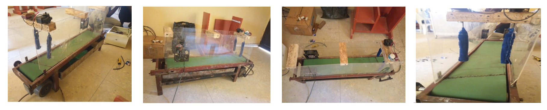
This research study was conducted at the general Mechatronics laboratory in the Department of Mechatronics Engineering, Federal University, Oye-Ekiti, Nigeria for a period of 6 months between March 2019 and early September 2019.
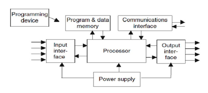
A Programmable Logic Controller (PLC) is a distinct form of microprocessor-based controller that uses programmable memory to store instructions and to implement functions as on/off control, timing, counting, sequencing, and arithmetic so as to control machines and processes. The basic functional component of a typical PLC is shown in Fig. 1 according to the pattern of Janik and Kupiec (2007) and Johnson et al., (2016).
PLC programming: A PLCs consist of input modules or points, it has a Central Processing Unit (CPU), and also output modules or points. In a PLC an input accepts a variety of digital or analog signals from various field devices (sensors) and converts them into a logic signal that can be used by the CPU. The CPU is the one to make decisions and executes control instructions based on program instructions in memory. The output modules convert control instructions from the CPU into a digital or analog signal that can be used to control various field devices (actuators). In this arrangement a programming device is then used to input the desired instructions. These input instructions determine what the PLC will do for a specific input. An operator interface device allows processing formation to be displayed and new control parameters to be entered which is similar to that of Vanamane and Mane (2012).
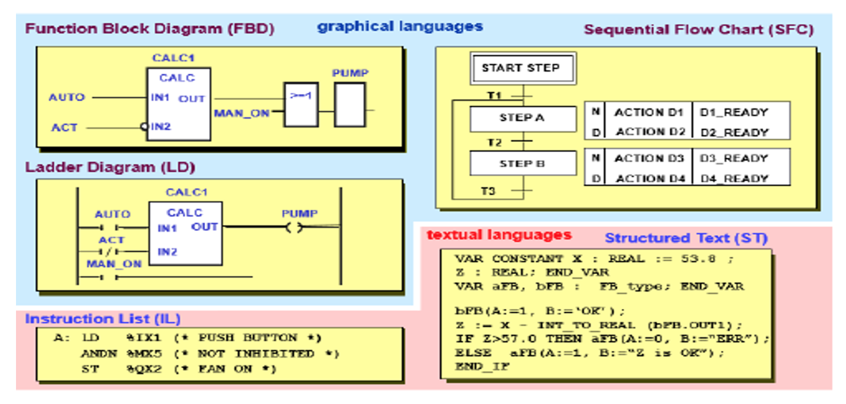
Programs for use with PLCs can be written in a number of formats. Most PLC manufacturers adopted ladder-logic for writing programs. However, each tended to develop its own varieties and so an international standard has been agreed upon for ladder programming and indeed all the methods used for programming PLCs just as noted by Johnson et al., (2016). The standard, published in 1993, is International Electrotechnical Commission IEC 61131-3 includes 5 programming languages, Fig. 2.
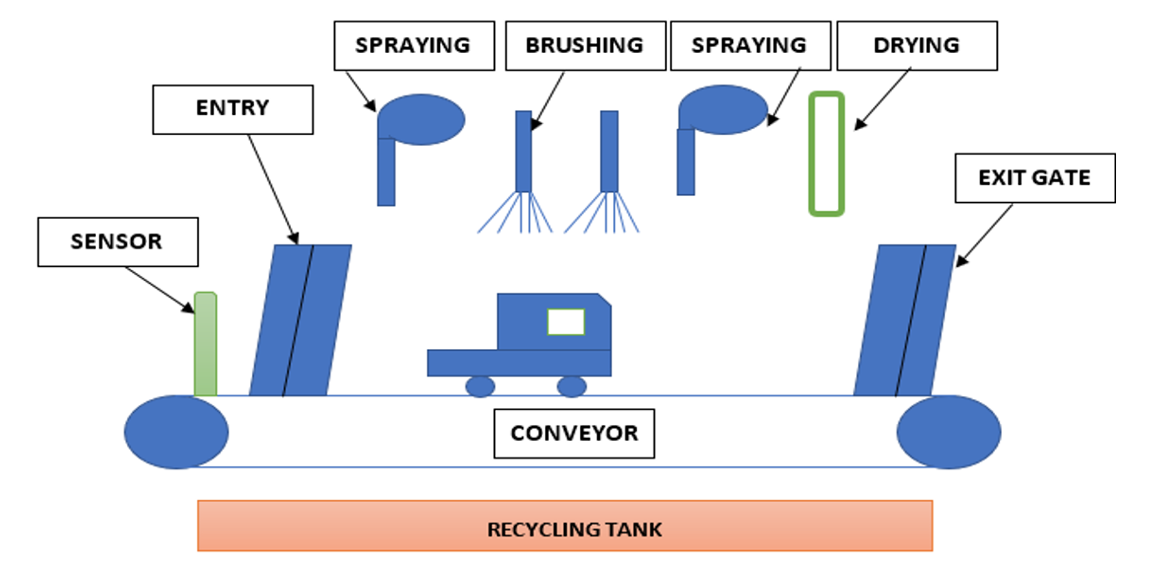
The system consists of a control panel where all electrical components like a power supply, PLC, VFD, Relay, Circuit breaker, contactor are boxed in. Also, the system involves movement with the use of a belt conveyor system to move the car from one station to another which is connected to an AC motor with a chain. It has different stations which have AC motor to drive the brushes, exhaust fan for drying and a pipelining system for the flow of liquid.
Conveyor belt system: This is responsible for moving the car from one station to another for various washing process.
Electrical control panel: This compartment houses all the electrical components required to make the system function. It is responsible for signifying the status of the washing process using LED indicator and controlling the process using several push buttons.
Electric motor: This is the prime mover for the machine which turns the chain resulting to the movement on the conveyor system.
Frame: This supports the machine and it provides a framework to house the entire washing system.
The automatic car washing system runs on electrical energy, once the electric motor is connected to the source of electric power it turns the chains connected from the motor to the roller of conveyor belt which in turn moves the belt of the conveying system to transport the car from one washing station to another performing its process as shown in Fig. 3.
Result analysis:
Design calculation for conveyor:
Motor power = 5.0 kw
Synchronous speed (motor rpm) = 1400 rpm (medium)
Belt width (m) = 7.7 cm = 0.077 m
Length of a conveyor = 106 cm = 1.06 m
Conveyor Belt Length = 93 cm = 0.93 m
Basic belt length = 2 × conveyor belt length = 2 × 93 = 1.86 m
Roller diameter = 40 mm = 0.04 m
Belt speed = v = $\pi$ × Diameter $\pi$ × 0.04 = 0.12 m/sec
Conveyor capacity:
$ C = \frac {C_T × P × C_F × V} {1000} $
where
C: Capacity in tonnes/h of a belt conveyor which consists of 3 equal roller idlers
$C_T$: The Capacity of troughed belts for 3 roll length idler = 175
P: The material density in kg/m3 = 100 kg/m3
$C_F$: Capacity Factor = 1.0
V : Belt speed = 0.12 m/sec
Conveyor capacity:
$ C = \frac {175 × 1000 × 1 × 0,12} {1000} = 21\ tonnes/hr $
***The conveyor consisting of 3 equal rollers idlers is 21 tonnes/h
Load due to conveyed materials mm:
$ Conveyor capacity (C) = 21\ tonnes/h $
$ V = belt speed = 0.12 m/sec $
$ m_m = \frac {C} {3.6 × v} $
$ m_m = \frac {21} {3.6 × 0.12} = 48.61\ kg $
Torque calculation:
$ Torque\ (T) = \frac {1} {2} D(F + \mu Wg) $
where,
D = Roller diameter = 0.04 m
F = m × g
M = Weight of the material and belt = 25 kg
G = $9.81\ m/{sec}^2$
F = 25 × 9.81 = 245.25 N
W = Weight of the material = 12 kg
$\mu$ = coefficient of fiction = 0.02
$ Torque\ (T) = \frac {1} {2}\ ×\ 0.04\ [245.25\ +\ (0.02\ ×\ 12\ ×\ 9.810)] $
$ Torque\ = 4.95\ Nm $
Belt tension: Belt tension at steady tension $(T_{ss})$
$ (T_{ss})\ =\ 1.37\ ×\ f\ ×\ l\ ×\ g\ ×\ (2\ ×\ M_i\ +\ (2\ ×\ M_b\ +\ M_m)\ cos(\theta)]\ +\ (H\ ×\ g\ ×\ Mm) $
given,
F : Coefficient of friction = 0.02
L : Length of conveyor belt = 0.93 m
G : Acceleration due to gravity = $9.81\ m/{sec}^2$
$ M_i $ : Load due to the idlers = 12 kg
$ M_b $ : Load due to belt: 25 kg/m
$ M_m $ : Load due to conveyed materials = 48.6 kg
$\theta$ : Angle of inclination of the conveyor = 0
H : Vertical height of the conveyor = 0.26 m
Idler spacing : 1.2 m
Belt power: The power at the drive pulley is:
$ P_p = \frac {T_{ss}\ ×\ v} {1000}\ = \frac {154.6\ ×\ 0.12} {1000}\ = 0.17\ kW $
$ Minimum\ power\ (P_{min})\ =\ \frac {P_p} {n} $
$ n\ =\ Drive\ efficiency\ =\ 0.05 $
$ Minimum\ power\ (P_{min})\ =\ \frac {0.17} {0.05}\ =\ 3.4\ kW $
Assumption:
$ M_i:\ Load\ due\ to\ idlers\ =\ \frac{Mass\ of\ a\ set\ of\ iflers}{idler\ spacing\ } = \frac{14.4kg}{1.2} = 12kg $
$M_b$ : Load due to belt: 25 kg/m
Mass of a set of idler = 14.4 kg
$ (T_{ss})\ =\ 1.37\ ×\ 0.02\ ×\ 0.93\ ×\ 9.81\ [2\ \times\ 12\ +\ (2\ \times\ 25\ +\ 48.6)\ cos(0^0)]$
$ ~~~~~~~~~~~~~~~~~~~~+\ [0.26\ ×\ 9.81\ ×\ 48.6] $
$ ~~~~~~~~~=\ 30.6474\ +\ 123.96 $
$ ~~~~~~~~~=\ 154.6\ kN$
Idler spacing = 1.2 m (For standard 3 idler rollers of equivalent length, the most recognized trough point is 350. So, CT = 350/2 = 175 is used).
During the start of the conveyor system, the tension in the belt will be much higher than the steady state. The belt tension while starting is:
$T_s\ =\ T_{ss}\ \times\ K_s $
$K_s$ = Start up factor (1.08)
$T_s\ =\ 154.6\ ×\ 1.08\ =\ 166.97\ kN$
Belt width (m) = 0.077 m
Length of conveyor (m) = 1.06 m
Length of the conveyor belt = 0.93 m
Basic belt length (m) = 1.86 m
Belt speed (m/sec) = 0.12 m/sec
Height of conveyor (m) = 0.26 m
Angle of inclination $(^o) = 0^o$
Conveyor capacity (tonnes/h) = 21 tonnes/h
Belt tension while starting (KN) = 166.97 KN
Belt tension at steady state (KN) = 154.6 KN
Load due to idlers (kg/m) = 12 kg/m
Load due to belt (kg/m) = 25 kg/m
Load due to materials conveyed = 48.6 kg/m
Power at drive pulley (KW) = 0.17 KW
Drive efficiency = 0.05
Idler spacing (m) = 1.2 m
Power required by conveyor = 5.0 KW
Torque (Nm) = 4.95 Nm
Material density (kg/m3) = 1000
Coefficient of friction = 0.02
Belt thickness (mm) = 1
Capacity factor = 1.0
Roller diameter (mm) = 40
Results And Discussion
The outcome of the testing process carried out on the car washing process on the system is given in the Table 1 and 2. The time taken to move the car to be washed from entry point to the washing unit is measured with a stop watch. This is similar to work of Singh et al., (2018) that uses a PLC to set the time taken to move the car to the wash room. The velocity of the conveyer belt is calculated from the reduced driving speed of 14 Hz of the system. The total time recorded for completion of the car washing is also recorded for various cars. Figure 4 represents the time analysis of the washing process. Total time consumed to complete the washing operation = Time at conveyer belt + Time at washing unit + delay, this is also in line with Oyeleke et al., (2014) in their work the development of a fruit washing machine. Delay time is the time taken for the car to move up and down the bridge of the washing station.
Successful experimental results were obtained from the previously described scheme indicating that the PLC can equally be used in automated conveyor belt systems. Consequently, the monitoring control system of the induction motor by PLC proves its high accuracy in speed regulation at constant-speed-variable-load operation. Each rung of the program was executed perfectly which resulted to the operation of the required process at its respective station when the desired input is true. Initially when the supply is on, the VFD will start and the belt motor will be driven through the VFD. The VFD operated at a working frequency of 14 Hz for the required speed of the motor. By using PLC control the efficiency obtained is increased as compared to the open-loop configuration of the induction motor fed by an inverter.
| Task | Time (sec) | Velocity (m/sec) | Distance travelled (mm) |
|---|---|---|---|
| Brushing | 15 | 30 | |
| Rinsing | 10 | 30 | |
| Drying | 20 | 35 | |
| Total duration | 45 | 95 |
| Type of car | Time at conveyor | Delay time (sec) | Total time (sec) |
|---|---|---|---|
| Light weight car | 45 | 6 | 51 |
| Delay time: Time taken for the car to move up and down the bridge of the washing station | |||
Conclusion
We live in a constantly changing world; the progress never stops. Automation was created to reduce manpower, to make production process easier and increase its quantities at a shorter time. Automation can be experienced in different aspect of life especially transportation, as it is noted to be the world’s oldest humankind’s activity, was very important field of production in past, it is so nowadays and will be in the future.
A PLC based machine designed specifically for washing the exterior of vehicles and also reducing water wastage by recycling. The automatic car washing system performs satisfactorily. It is efficient, easy to operate, cheap to maintain, low power consumption, high accuracy, requires little human interference and can be easily programmed. These features make it particularly suitable for the informal sectors like filling station, supermarket and mall where it can be quickly accessed and use. Its short washing operation duration when compared to other means of car washing makes it a very viable business because people want their car washed quickly and efficiently without causing damage to it and without the fear of theft. It also reduced the issue of water wastage by increasing it recycling activities. One great advantage to be derived from the use of the system is that the process is automated. The simplicity of operation of the machine ensures that no special technical expertise is needed in order to operate the system. When the machine is well maintained, its durability is guaranteed. The machine maintenance cost is also lower when compared with existing washing means.
The PLC based automatic car washing system will also contribute favorably to environment and economic issues. The modification introduced in the design plan and operation process of the automatic car washing system, if implemented will be beneficial and advantageous in the following:
- The issue of water pollution in the environment would be reduced.
- The income generated from this business venture would be boosted because the car washing process is done in a short period of time and considering it is an automatic car wash system, it can wash as many cars as possible efficiently without the fear of errors.
- The PLC system requires little maintenance cost.
Acknowledgment
The authors will like to appreciate Federal University Oye-Ekiti and the Department of Mechatronics Engineering for the teamwork. Also, we are thankful to Mr. Adegboyega Otenaike for technical inputs during the practical implementation.
Author Details
1Department of Mechatronics Engineering,
2Department of Mechanical Engineering, Federal University Oye-Ekiti, Nigeria
References
Hashim, N.M.Z., M.H.A. Halim, H. Bakri, S.H. Husin and M.M. Said, 2013. Vehicle security system using Zigbee. Int. J. Sci. Res. Publ., 3(9).
Janik, H. and A. Kupiec, 2007. Trends in modern car washing. Pol. J. Environ. Stud., 16(6).
Johnson, C.D., D.A. Mhaske, R.G. Bhavthankar, A.R. Saindane and D.J. Darade, 2016. PLC based car washing system. Int. J. Innov. Res. Electr. Electron., Process Kailash Sharma, 2018.
Oyeleke, F.I., A.M. Olaniyan, M.O. Sunmonu and S.K. Oyeniyi, 2014. Development of a fruit washing machine. J. Agric. Eng. Technol., 22(1): 29-36.
Pansare, A. and P. Yadav, 2015. PLC based automatic car washing system. Int. J. Adv. Eng. Res. Dev., 2(4).
Singh, R.D., S. Nigam, S. Aggrawal, M.R. Neelgar, S. Kaura and K. Sharma, 2018. Design and implementation of automatic car washing system using PLC. Int. Res. J. Eng. Technol., 5(05): 4183-4185.
Sorkhabi, A.H.D. and B. Khazini, 2013. Manufacturing of full automatic carwash using with intelligent control algorithms. Int. J. Mech. Aerospace Ind. Mech. Eng., 7(3).
Subramanian, G., K.T. Raja, K.S. Gowtham Babu and T. Devashena, 2015. Simulation of automatic car washing using PLC. Int. J. Sci. Res. Dev., 3(01).
Texas, 2012. Research on Hand Washing vs Automatic Washing. International Carwash Association with University of Texas at Arlington.
Vanamane, S.S. and P.A. Mane, 2012. Design, manufacture and analysis of belt conveyor system used for cooling of mould. Int. J. Eng. Res. Appl., 2(3): 2162-2167.
Vidyasagar, K., R. Prasad and P. Nagasekhar, 2015. RFID-GSM autonomous car washing system. Int. J. Comput. Appl., 121(2).
Zhou, K.L., X.X. Liu, Y.F. Zhang and S. Liu, 2016. Research and design of self-service car-washing system based on ARM11 [J]. Trans. Microsyst. Technol., 6: 107-108.
Rights and permissions
Open Access: This article is licensed under a Creative Commons Attribution 4.0 International License, which permits use, sharing, adaptation, distribution and reproduction in any medium or format, as long as you give appropriate credit to the original author(s) and the source, provide a link to the Creative Commons license, and indicate if changes were made. The images or other third-party material in this article are included in the article’s Creative Commons license, unless indicated otherwise in a credit line to the material. If material is not included in the article’s Creative Commons license and your intended use is not permitted by statutory regulation or exceeds the permitted use, you will need to obtain permission directly from the copyright holder. To view a copy of this license, visit http://creativecommons.org/licenses/by/4.0/
Cite this Article
Matthew O. Arowolo, Bayode J. Olorunfemi and Abiodun M. Adebimpe, 2020. Development of a Programmable Logic Control-Based Automatic Car Washing System. Research Journal of Applied Sciences, Engineering and Technology 17: 88-93. http://doi.org/10.19026/rjaset.17.6045
Received
Accepted
Published
December 16, 2019
April 8, 2020
June 15, 2020
DOI: http://doi.org/10.19026/rjaset.17.6045
Sections
Abstract
Keywords
Introduction
Materials and Methods
PLC programming
Conveyor belt system
Electrical control panel
Electric motor
Frame
Result analysis
Conveyor capacity
Load due to conveyed materials mm
Torque calculation
Belt tension
Belt power
Assumption
Results And Discussion
Conclusion
Acknowledgment
Author Details
References
Rights And Permissions
Cite This Article