Abass, I.K., 2013. Studying some of the geotechnical properties of stabilized Iraqi clayey soils. Eng. Tech. J., 31(6).
Effect of Silica Fume on the Shear Strength of Cohesionless Soil
Research Journal of Applied Sciences, Engineering and Technology 2020 18: 1-11
Cite This ArticleAbstract
Utilization of waste materials in geotechnical applications reduces the environmental problems of factories wastes. Silica fume is a by-product of the extraction of silicon or ferrosilicon manufacturing. Using silica fume as an additive to the soil can significantly increase the strength and decrease the permeability of the mixture.In this study silica fume is used to improve the mechanical properties of cohesionless soil, with special attention when used as backfill material for reinforced earth retaining walls. Biaxial geogrid prototype was used as reinforcement sheets in prepared bed of sand-silica fume mixture. The effect of adding silica fume was evaluated based on the results of Pull-out tests under various overburden pressures.From this study it was concluded that, adding silica fume to the sand had reduced the pull-out displacement of the geogrid by about 30 to 91% depending on the applied overburden pressure. That interlocking between the sand and silica fume particles is the main cause of densifying the sand by minimizing the lateral movement of the particles. Reduction in geogrid elongation reflects the increase in shear resistance interaction of the geogrid-backfill, and consequently the increase in the stability of the reinforced earth retaining walls under static and earthquake actions.
Keywords:
Introduction
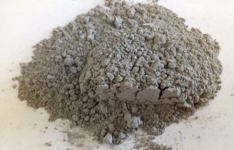
Silica Fume (S.F) or microsilica is a by-product in the manufacture of silicon and ferrosilicon alloys. It is an ultra-fine powder consisting of nearly spherical particles around 100 times smaller than a grain of cement, and 10 to 20 times finer than fly ash as shown in Fig. 1.
Silica fume is pozzolanic because of its high silica content and its high specific surface area (Moayed et al., 2009; Abass, 2013). Nearly 100,000 tons of silica fume are produced each year on the world. In the past, it was ejected as waste material from plant chimneys leading to the air pollution and environmental problems. Now days, silica fume is used to improve the mechnical properties of geotechnically problematic soils (Akbulut and Saglamer, 2003; Kalkan, 2009a; Harichane et al., 2011; Heba, 2011). Grouts for micropiles with a content of silica fume up to 10% and exposed to an aggressive sulphate medium, have a better behaviour in the very long-term, compared to grouts prepared using sulphate-resisting Portland cement (Ortega et al., 2017). Kalkan, (2009b) found that, silica fume as waste material can be successfully used to reduce the development of desiccation cracks in compacted clayey liner and cover systems.
McKennon et al. (1994) found that, addition of microsilica is an important additive to control the formation of deleterious products such as Ettringite in sulfate bearing soils stabilized with lime or Portland cements. Bagherpour and Choobbasti, (2003) studied the stabilization of fine-grained soils by adding microsilica and lime, the results showed significant increases in the unconfined compression strength.
Kalkan and Akbulut, (2004) and Al-Soudany, (2017) reported the positive effects of silica fume on the permeability, swelling pressure and compressive strength of natural clay. Kalkan, (2009a) Kalkan, (2009b) and Kalkan, (2011) studied the effect of silica fume on the geotechnical properties of fine-grained soils exposed to freeze and thaw, the results indicated that, using silica fume had greatly decreased the effects of freezing and thawing cycles on the unconfined compressive strength and permeability.
The interaction shear strength between the backfill and geogrid is the main factor controls the stability of reinforced earth retaining walls. As a substitution forcement typically only 4-10% by weight of cement is substituted (Weaver and Bruce, 2007). Only small amounts of silica fume are substituted because it has been shown that 4-10% is the optimal amount to improve grout strength and elastic modulus. They also observed that, if silica fum is added in a condensed form such as pellets, the pozzolanic reactivity is reduced.
In this study, pull-out experimental model was used to investigate the effect of adding silica fume to sandy soil as backfill material reinforced with geogrid. The prepared sand was mixed with 5% silica fume, and the horizontal displacement of geogrid due to pull-out testing was measured under different effective overburden pressures. The effect of silica fume was evaluated based on comparing the results of testing the pull out resistance of geogrid for pure sand and silicafume-sand backfill mixture. The shear strength ofthe used sand and silica fume-sand mixture was measured using direct shear box test.
Experimental Work
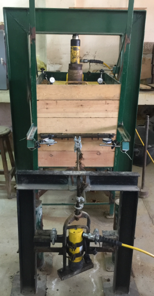
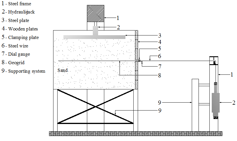
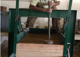
Pull-out model test: Pull-out tests were carried out according to ASTM D 6706-0101 ASTM, (2006), with some modifications to suit the laboratory preparations. The pull-out test box and the loading frame used in this research to study the soil-geogrid interaction are shown in the overview photo of Fig. 2, and schematic drawing of Fig. 3 (Anas et al., 2016).
The inner dimensions of the steel box are 1000 mm (length) × 700 mm (width) × 700 mm (height). Two steel L-angels were welded parallel to the front face performing an edge channel to accomodate 6 wooden plates having a thickness of 2.5 cm which represented a retaining wall for the tested soil. At a height of 30 cm, an opening of 60 cm (width) × 2 cm (height) was provided at the front of the box to facilitate the pulling out of the geogrid sheets.
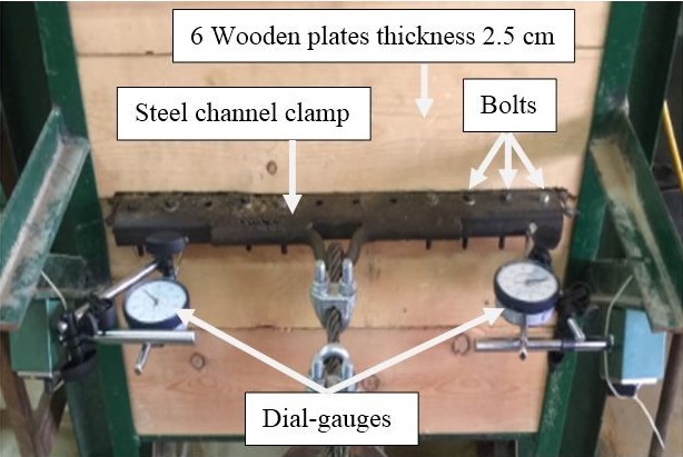
A steel channel clamp was utilized for holding the geogrid and was fixed to the geogrid by 12 bolts as shown in Fig. 4.
The vertical stress was applied by a manually-controlled hydraulic jack having the capacity of 250 kN and was placed on the steel plate. A steel frame, asshown in Fig. 2, was mounted over the pull-out box to give the required reaction. Overburden load was uniformly distributed by placing a steel plate that has dimentions of 730 mm (length) × 490 mm (width) ×40 mm (depth). A manually-controlled hydraulic jack was used for applying the pull-out load. The pull-out loadwas applied to the geogrid via a steel wire attached to the clamp and the reaction was taken from the groundby a steel frame mounted in front of the pull-out box. The front displacements were measured using two dial-gauges so that average values can be calculated.
Test materials:
Soil: In this study, uniformly Graded Sand (G.S) was used as backfill material prepared in model test box.
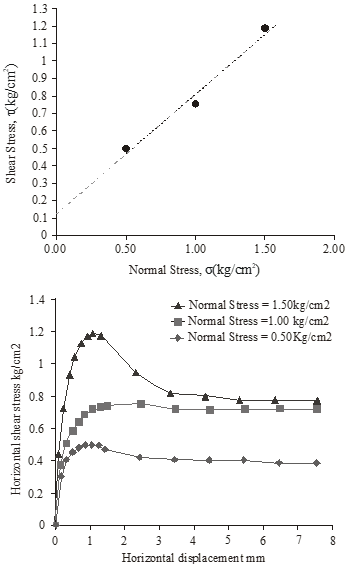
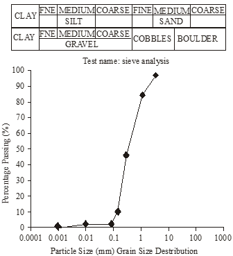
The basic physical and mechanical properties of the sand were determined, and the tests showed that, according to the followed test procedures and compaction effort, the maximum dry density of the sand that could be reached in the model tank was about 16.5 kN/m3, and the direct shear tests showed the corresponding internal of friction angle (φ) of about 35°. Figure 5 illustrates the relationship between Normal and Shear stress to obtain shear strength parameters. Therefore, the prepared backfill sand is at the boundary of medium dense to dense state. Sieve analysis of sand as show in Fig. 6.
In this study, uniformly graded sand was used as backfill material prepared in model test box. The basic physical and mechanical properties of the sand weredetermined, and the tests showed that, according to the followed test procedures and compaction effort, the maximum dry density of the sand that could be reached in the model tank was about 16.5 kN/m3, and the direct shear tests showed the corresponding internal of friction angle (φ) of about 35° as shown in Fig. 4. Therefore, the prepared backfill sand is at the boundary of medium dense to dense state.
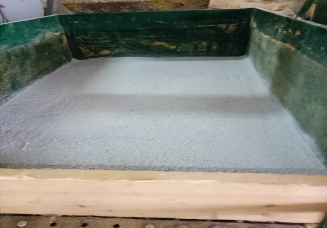
Characteristics of silica fume: Silica Fume (S.F) was obtained from Egyptian Company for Ferroalloys (alferrosilcon), Edfo factory, Aswan, Egypt. The micro silica fume has specific gravity of about 2.12 and particle size $ \lt 1 \; \mu m $ (Gupta and Sharma, 2014), and the chemical composition of silica fume is listed in Table 1. The test backfill was prepared by mixing the sand with 5% silica fume by weight. The surface of prepared sand and silica fume is shown in the photo of Fig. 7.
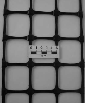
Geogrid: The prototype of geogrid used in this study was manufacture to represent a conventional commercial Biaxial Geogrid with aperture size of 50×50 mm and a thickness of 2 mm as shown in Fig. 8. When granular material is compacted over these grids, it partially penetrates and projects through the apertures to create a strong and positive interlock.
Model test preparation:
- The lower half of the backfill was prepared by manually pouring the sand or sand+5% silica fume mixture (Where the sand is mixed with silica fume mechanically before being placed in the test apparatus and for the specified) inside the testing box, and placed in 6 layers each with 10 cm in. Every layer had been compacted using damping desk with weight of 7.50 kg (Fig. 9), the dropping height of the damping disc was about 300 mm above the backfill surface, each layer was compacted by 2 drops of the disc damping. It worthnoting that, previous trials to increase the number of blows more than two drops had led to very dense backfill, and the geogrid sheet was subjected to rupture during the pull out test, and the required pulling force was higher than the capacity of the test hydraulic jack.
- When the sand reached a height of 30 cm, the geogrid sheet was fixed to the clamping plate and placed over the surface of the sand. The sand backfill was then completed with more three compacted layers.
- Dial gauges were attached to the clamping plate to measure the front displacements.
- The surface external surcharge was applied and kept constant using hydraulic jack resting over a rigid steel plate on the backfill surface.
- The pull-out load test was applied in increments of 15 kN in each stage, the applied pull-out increment load was kept constant until gauge reading shows negligible rate, the recorded elapsed time for each increment of loading was about more or less 5 min. The pull-out load test used were (30-45-60) kN.
- The lower half of the backfill was prepared by manually pouring the sand or sand+5% silica fume mixture (Where the sand is mixed with silica fume mechanically before being placed in the test apparatus and for the specified) inside the testing box, and placed in 6 layers each with 10 cm in. Every layer had been compacted using damping desk with weight of 7.50 kg (Fig. 9), the dropping height of the damping disc was about 300 mm above the backfill surface, each layer was compacted by 2 drops of the disc damping. It worth noting that, previous trials to increase the number of blows >2 drops had led to very dense backfill, and the geogrid sheet was subjected to rupture during the pull out test, and the required pulling force was higher than the capacity of the test hydraulic jack.
- When the sand reached a height of 30 cm, the geogrid sheet was fixed to the clamping plate and placed over the surface of the sand. The sand backfill was then completed with more three compacted layers.
- Dial gauges were attached to the clamping plate to measure the front displacements.
- The surface external surcharge was applied and kept constant using hydraulic jack resting over a rigid steel plate on the backfill surface.
- The pull-out load test was applied in increments of 15 kN in each stage, the applied pull-out increment load was kept constant until gauge reading shows negligible rate, the recorded elapsed time for each increment of loading was about more or less 5 min. The pull-out load test used were (30-45-60) kN.
Test loading: Six model tests were carried out to investigate the influence of adding Silica fume on the soil-geogrid interaction shear resistance. Three tests on pure sand backfill, and the other three tests on sand mixed with % silica fume. Testing wass performed under three different overburden pressures (q) of 18.22, 36.44 and 72.89 kN/m2, respectively. The total normal stress σn (kN/m2) acting on the geogrid is calculated using the following Eq. (1):
$ σn = γ_1h_1 + γ_2h_2 + q ~~~~~~~~~~~~~~~~~~~~~~~~ (1)$
where,
$ \begin{aligned}
γ_1 (kN/m^3) & : \text {The backfill density } \\
h_1 (m) & : \text {The height of soil above the geogrid} \\
γ_2 & : \text {The steel density } \\
h_2 (m) & : \text {The height of steel plate } \\
q (kN/m^2) & : \text {The applied external surcharge}
\end{aligned} $
| Pacification | Constituent | Specifications | Pacification | Constituent | Specifications |
|---|---|---|---|---|---|
| Bulk density | 270 kg/m3 | (260-320) kg/m3 | Bulk density | 270 kg/m3 | (260-320) kg/m3 |
| $SiO_2$ | 93.79% | Min. 92% | $Na_2O$ | 0.43% | Max. 0.8% |
| $Fe_2O_3$ | 1.48% | Max. 1.5% | Cl | 0.05% | Max. 0.1% |
| $Al_2O_3$ | 0.36% | Max. 1.0% | Specific surface area (BET) | 19.90 m2/g | Min. 15 m2/g |
| $MgO$ | 0.41% | Max. 0.6% | PH | 6.80 | Max. 8.0 |
| $SO_3$ | 0.19% | Max. 0.6% | Color reflection | 47% | Min 45% |
| L.O.I | 1.63% | Max. 2.0% | C | 0.90% | Max. 1.5% |
| $H_2O$ | 0.25% | Max. 0.5% | Residual coarse particle | 0.85 | +0.045 in diameter 1.0 max |
| $K_2O$ | 0.62% | Max. 1.3% | Cl | 0.05% | Max. 0.1% |
Test Results
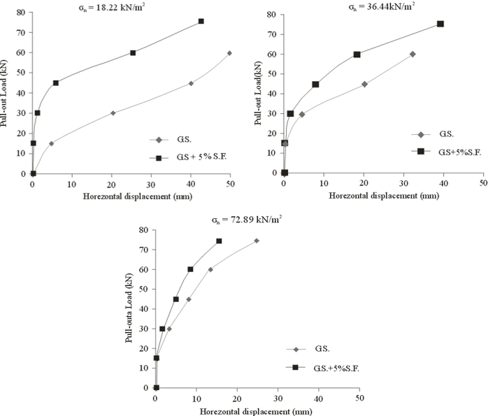
Displacement of geogrid: The Pull-out test was carried out on the geogrid, in case of pure sand and sand mixed with 5% silica fume, under different values of normal stress, and the results are as shown in theplots of Fig. 10. Comparison between the effect of adding silica fume on the elongation of geogrid sheets under the applied pull out loads is as listed in Table 2.
From Table 2 it can be observed that, adding silica fume had significantly reduced the elongation of geogrid sheet under the applied pull out loads. The reductions in geogrid displacement due adding silica fume decrease with the increase of the applied normal stress and pull out load. The displacement of geogrid under various applied normal stress and pull out loads was in the range of 2.50 to 50 mm in case of pure sand, while for sand +5% SF varied between 2 mm to 25 m. The reduction in geogrid displacement due to adding 5% silica fume was in the range of 30 to 91% with higher reduction for lesser normal stress and lesser pull out load, and vice versa.
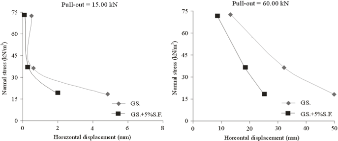
Normal stress and geogrid horizontal displacement: The relationship between normal stress and horizontal displacement at different values of Pull-out is illustrated in Fig. 11.
The results plotted in Fig. 11 and Table 3 Are listed in indicate that, the higher the normal stress the lesser of horizontal displacements. The relationship between the pull out force and the induced horizontal displacement is not in a linear relationship; when the applied pull out duplicated to four times i.e., from 15 to60 kN, under normal stress of 18.22 kN/m2 the horizontal displacement ratio increased by about 10 and 12 times for sand and sand +silica fume mixture respectively, while under = 72.89 kN/m2 it became 35 and 40 for sand and sand +silica fume mixture respectively.
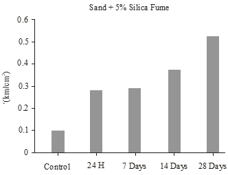
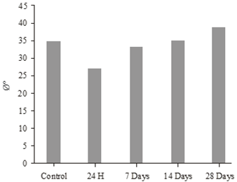
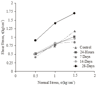
Effect of silica fume on shear strength parameters: Twelve samples were tested on 4 time stages (24 h, 7, 14 and 28 days, respectively) of sand + 5% silica fume. The samples were tested after mixing sand with silica fume by 5% using a shear box test. The purpose is to determinethe effect of silica fume with time and its effect on the values and coefficients of shear resistance.
Table 4 shows the effect of silica fume with time after mixing with sand by 5% as well as the shear resistance of sand only.
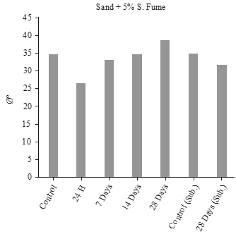
Figure 12 and 13 shows the values and coefficients of shear resistance with time for sand only and sand + 5% Silica fume.
Figure 14 shows the values of shear strength parameters ofsand only and sand + 5% silica fume with time.
Table 5 shows the results of the direct shear test for both sand and sand with 5% silica fume and the effect of time on the values of shear strength parameters.
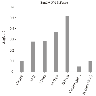
Effect of water on sand with silica fume on shear strength parameters: Six samples were tested on owntime stage(28 days) of sand + 5% silica fume. The samples were tested after mixing sand with silica fume by 5% using a shear box test. The sample was immersed in water.
The purpose is to determine the effect of water and silica fume with time and its effect on the values of shear strength parameters.
Table 6 shows the effect of water on sand with silica fume with time after mixing with sand by 5% as well asthe shear strength parameters of the samples in case of water flooding.
Effect of water on sand for shear strength parameters: Three samples were tested of sand only.The samples were tested using a shear box test. The sample was immersed in water.
Table 7 shows the effect of water on sand for the values of shear strength parameters in case of water flooding.
Table 8 shows the effect of silica smoke with the passage of time after mixing with the sand by 5% and submerged in water, as well as the shear resistance to sand only in the case of sand immersed in water.
Table 9 shows the effect of silica fume with time after mixing with sand by 5% as well as the shear strength parameters of sand only in the dry state of the samples and in the case of water flooding.
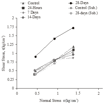
Figure 15 and 16 shows the values and shear strength parameters with time for sand only and sand + 5% Silica fume in the dry state of the samples and in the case of water flooding.
Figure 17 shows the values shear strength parameters of sand only and sand + 5% silica fume with time in the cases of dry state and submerged.
Table 10 shows the results of the direct shear test for both sand and sand with 5% silica fume and the effect of time on the values of shear strength parameters in the dry state of the samples and in the case of water flooding.
| Normal stress | $\sigma_n = 18.22 kN/m^2$ | |||
|---|---|---|---|---|
| Pull-out force (kN) | 30 | 45 | 60 | |
| Sand | $\Delta L$ | 20 mm | 40 mm | 50 mm |
| Sand + 5% SF | 1.80 mm | 6.0 mm | 25 mm | |
| Reduction | 91% | 85% | 50% | |
| Normal stress | $\sigma_n = 36.44 kN/m^2$ | |||
| Sand | $\Delta L$ | 5 mm | 20 mm | 32 mm |
| Sand + 5% SF | 1.80 mm | 8 mm | 20 mm | |
| Reduction | 64% | 60% | 37.50% | |
| Normal stress | $\sigma_n = 72.89 kN/m^2$ | |||
| Sand | $\Delta L$ | 2.50 mm | 8 mm | 13 mm |
| Sand + 5% SF | 2.0 mm | 5 mm | 9.0 mm | |
| Reduction | 40% | 37.5% | 30.7% | |
| Normal stress Pull out (kN) | $\sigma_n = 18.22 kN/m^2$ | $\sigma_n = 36.44 kN/m^2$ | $\sigma_n = 72.89 kN/m^2$ | |||
|---|---|---|---|---|---|---|
| Pull out (kN) | 15 | 60 | 15 | 60 | 15 | 60 |
| Displacement | Horizontal displacement $(\Delta L)$ | |||||
| Sand | 4.8 mm | 50 mm | 0.60 mm | 18 mm | 0.40 mm | 14 mm |
| $\Delta L$ (60/15) ratio | 10.42 | 30.00 | 35.00 | |||
| Sand + 5% SF | 2 mm | 25 mm | 0.40 mm | 18 mm | 0.20 mm | 8 mm |
| $\Delta L$ (60/15) ratio | 12.50 | 33.33 | 40.00 | |||
| Shear para. | Sand (S) | 24 H S + 5% S.F | 7 days S + 5% S.F | 14 days S + 5% S.F | 28 days S + 5% S.F |
|---|---|---|---|---|---|
| $c (kg/cm^2)$ | 0.1 | 0.28 | 0.29 | 0.37 | 0.52 |
| $\phi\deg$ | 35 | 27 | 33 | 35 | 39 |
| S: Sand only; S+5% S.F: Sand + 5% silica fume; H: Hour | |||||
| Soil | Sand | Sand + 5% silica fume | |||
|---|---|---|---|---|---|
| Time | - | 24 h | 7 day | 14 days | 28 days |
| C kg/cm2 | 0.1 | 0.28 | 0.29 | 0.37 | 0.52 |
| Ø˚ | 35 | 27 | 33 | 35 | 39 |
| Decreasing (c) % | - | - | - | - | - |
| Decreasing (Ø) % | - | 22.90 | 5.71 | - | - |
| Increasing (c) % | - | 280 | 290 | 370 | 520 |
| Increasing (Ø) % | - | - | - | - | 10.30 |
| Shear para. | 28 days S + 5% S.F (sub.) |
|---|---|
| c (kg/cm2) | 0.10 |
| ɸ° | 32 |
| Sub.: Submerged | |
| Shear para. | Sand (S) sub. |
|---|---|
| c (kg/cm2) | 0.05 |
| ɸ° | 35 |
| Shear para. | 28 days S + 5% S.F (sub.) | Sand (S) sub. |
|---|---|---|
| c (kg/cm2) | 0.10 | 0.05 |
| ɸ° | 32 | 35 |
| Shear para. | Sand (S) | Sand (S) sub. | 24 H S + 5% S.F | 7 days S + 5% S.F | 14 days S + 5% S.F | 28 days S + 5% S.F | 28 days S + 5% S.F (sub.) |
|---|---|---|---|---|---|---|---|
| c (kg/cm2) | 0.1 | 0.05 | 0.28 | 0.29 | 0.37 | 0.52 | 0.1 |
| ɸ° | 35 | 35 | 27 | 33 | 35 | 39 | 32 |
| Soil | Sand (S) | Sand (S) sub. | Sand + 5% silica fume | ||||
|---|---|---|---|---|---|---|---|
| Time | - | - | 24 h | 7 day | 14 days | 28 days | 28 days sub. |
| C kg/cm2 | 0.1 | 0.05 | 0.28 | 0.29 | 0.37 | 0.52 | 0.10 |
| Ø˚ | 35 | 35 | 27 | 33 | 35 | 39 | 32 |
| Decreasing (c) % | - | 50 | - | - | - | - | - |
| Decreasing (Ø) % | - | - | 22.90 | 5.71 | - | - | 8.75 |
| Increasing (c) % | - | - | 280 | 290 | 370 | 520 | - |
| Increasing (Ø) % | - | - | - | - | - | 10.30 | - |
Discussion
The interlocking between the sand and silica fume particles is the main cause of densifying the sand by minimizing the lateral movement of the particles. On the other hand, the movement of the cogs through the middle layers of sand, during pulling the geogrid out, resulted in a rarefaction in the layers and hence restricted the increase of the final soil density.
From the laboratory tests and the results presented, we conclude that the presence of silica fume has the presence of a cohesion between the sandy soil granules and therefore the presence of resistance more than the resistance of sandy soil grains alone, which confirms the presence of a clear effect of the addition of silica fume on the sandy soil in reducing the values of horizontal displacement at the normal stresses. Where the ratio of horizontal offset reduction to all laboratory experiments in the case of mixing sand with silica fume ranged from 36 to 98% of the case of sand alone.
The results also showed an effect on the values of shear strength parameters when adding silica fume to sand. The values of cohesion increased to 520% and the angle of internal friction values increased to 10.30%.
The results of the previous tests show that the effect of water on the sand sample only has no effect on the values of shear strength parameters. While water has an effect in the case of addition of silica fume to sand, where after 28 days found that the values of shear strength parameters are close or equal with the values of shear strength parameters for sand only without the addition of silica fume.
Conclusion
The following conclusions and recommendations are based on the experimental results carried out in this study, to the effect of adding silica fume on sand to the horizontal displacement, the conclusions are as follows:
- The addition of silica fume on the sand led to the reduction of the horizontal displacement of the geogrid with percentages ranging from 36-98% than the sand without adding silica fume.
- The higher the vertical stress, the less the horizontal displacement, whether the addition of silica fume or without addition.
- When adding silica fume to sand and increasing the value of vertical stress, the value of the horizontal displacement decreases by 36-98%.
- The highest values of pull-out resistance were obtained in case of the tested sand with the sand and silica fume and they are about 60% higher than these obtained when using the sand only.
- The maximum values of the achieved pull-out capacity in case of using the sand with silica fume are about 50% higher than these achieved when using the sand only.
- Addition of silica fume to sand increarced the value of weak cohesion in the sand up to 520%.
- Addition of silica fume to sand increased the value of internal friction of sand up to 10.30%.
- The effect of silica fume with time is positive with the values of shear strength parameters, especially in soil cohesion values.
- The effect of silica fume with time is positive with the values of the shear strength parameters, especially in the values of soil cohesion where the value of the cohesion increased by 520% and the value of the internal friction angle by 10.30% in the dry state.
- The values of shear strength parameters for sand were not affected either in dry or submerged conditions.
- Water should not be kept in soil when silica fume is added to it to take advantage of its effect on the values of shear strength parameters which have no value in the case of water reaching the soil.
Recommendations
Future studies on different soil types are recommended to study the effect of addition of silica fume with varying mixing ratios.
Acknowledgement
The experimental work of this study was carried out at the Soil Mechanics Laboratory of civil Eng. Department, Al-Azhar University, thanks for the laboratory staff and technicians, and also for the help of material lab technicians.
Author Details
1Department of Civil Engineering, Faculty of Soil Mechanics, Al-Azhar University, Nasr City, Cairo, Egypt
References
Akbulut, S. and A. Saglamer, 2003. Improvement of hydraulic conductivity of soils by grouting. P. I. Civil Eng. Ground Improv., 7(4): 157-164.
Al-Soudany, K.Y., 2017. Improvement of expansive soil by using silica fume. Kufa J. Eng., 9(1): 222-239.
Anas, I., A. Farouk, M.B. El Sideek, A.R. Hassan and Y. Mowafy, 2016. An innovative shape of geogrid to increase pull-out capacity. IOSR J. Mech. Civil Eng. (IOSR-JMCE), 13(4): 72-79.
ASTM, 2006. Annual Books of ASTM Standards, Construction: Soil and Rock (I). American Society for Testing and Materials, Philadelphia, PA, D 4439.
Bagherpour, I. and A.J. Choobbasti, 2003. Stabilization of fine-grained soils by adding micro silica and lime or micro silica and cement. EJGE, Vol. 8.
Gupta, C. and R.K. Sharma, 2014. Influence of micro silica fume on sub grade characteristics of expansive soil. Int. J. Civil Eng. Res., 5(1): 77-82.
Harichane, K., M. Ghrici, S. Kenai and K. Grine, 2011. Use of natural pozzolana and lime for stabilization of cohesive soils. Geotech. Geol. Eng., 29(5): 759-769.
Heba, A., 2011. Effect of fly ash and silica fume on compressive strength of self-compacting concrete under different curing conditions. Ain Shams Eng. J., 2(2): 79-86.
Kalkan, E. and S. Akbulut, 2004. The positive effects of silica fume on the permeability, swelling pressure and compressive strength of natural clay liners. Eng. Geol., 73(1-2): 145-156.
Kalkan, E., 2009a. Effects of silica fume on the geotechnical properties of fine-grained soils exposed to freeze and thaw. Cold Reg. Sci. Technol., 58(3): 130-135.
Kalkan, E., 2009b. Influence of silica fume on the desiccation cracks of compacted clayey soils. Appl. Clay Sci., 43(3/4): 296-302.
Kalkan, E., 2011. Impact of wetting-drying cycles on swelling behavior of clayey soils modified by silica fume. J. Appl. Clay Sci., 52(4): 345-352.
McKennon, J.T., N.L. Hains and D.C. Hoffman, 1994. Method for stabilizing clay bearing soils by addition of silica and lime, Patent Cooperation Treaty (PCT), Patent Classification C09K 17/00, Publication Number: WO 94/06884.
Moayed, R.Z., S. Heiderari and M. Sayadi, 2009. Stabilization of saline soil with lime and silica fume. Proceeding of the 2nd International Conference on New Developments in Soil Mechanics and Geotechnical Engineering, Near East University, Nicosia, North Cyprus.
Ortega, J.M., M.D. Esteban, R.R. Rodríguez, J.L. Pastor, F.J. Ibanco et al., 2017. Influence of silica fume addition in the long-term performance of sustainable cement grouts for micropiles exposed to a sulphate aggressive medium. Materials, 10(8): 890.
Pinto, M.I.M., 2003. Discussion of applications of geosynthetics for soil reinforcement. Ground Improv., 7(2): 61-72.
Weaver, K. and D. Bruce, 2007. Grouting Materials. Dam Foundation Grouting: Revised Edn., pp: 104-108.
Rights and permissions
Open Access: This article is licensed under a Creative Commons Attribution 4.0 International License, which permits use, sharing, adaptation, distribution and reproduction in any medium or format, as long as you give appropriate credit to the original author(s) and the source, provide a link to the Creative Commons license, and indicate if changes were made. The images or other third-party material in this article are included in the article’s Creative Commons license, unless indicated otherwise in a credit line to the material. If material is not included in the article’s Creative Commons license and your intended use is not permitted by statutory regulation or exceeds the permitted use, you will need to obtain permission directly from the copyright holder. To view a copy of this license, visit http://creativecommons.org/licenses/by/4.0/
Cite this Article
Mahmoud Abo Bakr El Sideek, 2020. Effect of Silica Fume on the Shear Strength of Cohesionless Soil. Research Journal of Applied Sciences, Engineering and Technology 18: 1-11 http://doi.org/10.19026/rjaset.18.6058
Received
Accepted
Published
April 10, 2020
April 30 2020
March 25, 2021
DOI: http://doi.org/10.19026/rjaset.18.6058
Sections
Abstract
Keywords
Introduction
Experimental Work
Pull-out model test
Test materials
Soil
Characteristics of silica fume
Geogrid
Model test preparation
Test loading
Test Results
Displacement of geogrid
Normal stress and geogrid horizontal displacement
Effect of silica fume on shear strength parameters
Effect of water on sand with silica fume on shear strength parameters
Effect of water on sand for shear strength parameters
Discussion
Conclusion
Recommendations
Acknowledgement
Author Details
References
Rights And Permissions
Cite This Article